English
 العربية
 Nederlands
 Français
 Deutsch
 Italiano
 日本語
 한국어
 Polski
 Português
 Русский
 Español





A sheet metal enclosure fails on the drawing, not the shop floor: cracked corners, distorted holes and mismatched panels usually trace to decisions made before the plate is cut. This guide covers the DFM rules that keep an aluminum box manufacturable — bend radius, flange length, hole placement, springback, joining, corner construction and tolerances — with concrete numbers you can use in CAD.
Sheet Metal Box Design Overview
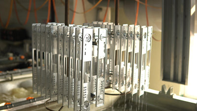
A fabricated box follows four steps: laser or blanking cutout, press-brake forming, joining (welding, riveting or fasteners), then surface treatment and assembly. Each step narrows the choices available to the designer, so the drawing has to carry the decisions that matter.
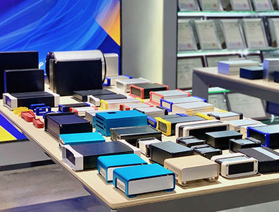
Material choice sets the rest of the design. 5052-H32 aluminum is the standard bending alloy: ductile, corrosion-resistant, tolerant of tighter radii. 6061-T6 aluminum is stronger but temper-hardened, needing a larger radius and springback allowance, so it is usually reserved for machined panels rather than bent housings. Typical aluminum enclosure thickness runs 1.0–2.5 mm: below 1.0 mm the large faces lack rigidity, above 2.5 mm bend force and springback rise sharply. Browse the S series sheet metal rackmount boxes or the full sheet metal enclosure range to see how these trade-offs appear in finished products.
Bend Radius & Minimum Flange
Two rules govern every bend: the inside radius must not crack the outer fiber, and the flange must be long enough for the brake tooling to grip. Model the bend as an inside radius in CAD — never a zero-radius sharp corner, which the press brake cannot form and which concentrates stress in service.
| Design feature | 5052-H32 aluminum | 6061-T6 aluminum | Rule of thumb |
| Inside bend radius R | ≥ 1.0 × T | ≥ 1.5–2.0 × T | R = inside radius, T = sheet thickness |
| Minimum flange length | ≥ R + 2T | ≥ R + 2T | Shorter flanges slip in the die and form poorly |
| Radius consistency | One R per part | One R per part | Fewer radii mean fewer tool changes |
| Grain direction | Bend across the grain | Bend across the grain | Bending with the grain risks edge cracking |

Keep one radius across the enclosure: mixing 1.0T and 2.0T forces tool changes and adds cost. Bend across the rolled grain; bending with the grain can crack the outer fiber, especially in T6. For very short flanges, let the adjacent panel absorb grip through an over-bend and secondary straightening rather than asking the brake to form a sub-minimum flange.
Hole & Slot Design Rules
Holes and slots inside the bend's deformation zone distort as the flange forms. The rules below keep every feature outside that zone, or place it where the shop can form it after bending.
Hole-to-Bend Distance
Keep the center of any hole at least 3T + R from the bend line as a conservative value; 2.5T + R is the lower limit for small, non-critical holes. Closer than that, the pull of the bend elongates the hole into an oval and pulls its edge toward the flange. If a connector or mounting hole has to sit near a bend, do one of two things: drill or punch it after the flange is formed, or add a bend relief between the feature and the bend line so the deformation zone cannot reach it.

Hole-to-Edge Distance
The hole center should sit at least 1.5D from a free edge, where D is the hole diameter. Closer to the edge, the cutout tears out during blanking. Other feature rules for thin aluminum:
Minimum punched or laser hole diameter is approximately one sheet thickness; below that, the slug and burr control become unreliable. Slot width should also be at least T — a slot narrower than the plate thickness loses stability in cutting. For threaded fasteners in 1.0–2.0 mm aluminum, do not tap the sheet directly: specify a rivet nut, clinch stud or reinforced boss, because direct tapping in thin sheet strips under torque. Leave clearance around every hole for the fastener head, washer and wrench access, not just for the screw itself.
Springback Compensation
Springback is the elastic recovery that opens a bend slightly after the brake releases the part. Aluminum springs back less than stainless steel but more than mild steel, and heat-treated T6 stock recovers more than H32 temper. The angle you set on the die is therefore not the angle the part ends up at.
Compensation happens in three ways, chosen with the shop: overbending the die angle so the part springs back to target, radius and tooling adjustment tuned to the actual K-factor of the alloy and thickness, and coining or flattening the bend zone to lock the angle down. Thick sheet, hard temper and tight radii all increase springback. The reliable workflow is to form a first sample, measure the actual angle, then transfer the compensation back into the tooling — do not rely on a generic angle table for T6 or 2.5 mm plate. Our bending enclosure customization service and laser and bending equipment cover this forming step in production; the sheet metal blog collects the underlying mechanics on material behavior in bending.
Welding & Fastening Design
For an aluminum enclosure, choose mechanical joining first and welding second. Bolts, rivet nuts, clinch studs and rivets hold tolerances, stay serviceable, and avoid the heat-affected zone that aluminum welding brings. Aluminum TIG or MIG welding introduces heat distortion, burns and oxidation that have to be ground and dressed before anodizing or powder coating, and any weld near a bend line or a hole pulls the surrounding geometry out of position.
Where welding is unavoidable, favor a lap joint over a butt joint, keep weld beads away from bend lines and cutouts, and specify which seams must be continuous for IP sealing versus which are structural only. Design the weld allowance into the flange width so dressing the bead does not eat into the visible face. For fasteners, match the insert to the sheet: a rivet nut in thin wall, a clinch stud where a threaded standoff is needed, and a clearance hole sized for the head and washer. Reserve conductive or grounding surfaces away from painted and anodized areas so the box can bond to the equipment ground.
Corner Joint Designs
Four corner constructions are common on electronics boxes. The choice trades strength, appearance, sealing and cost:
| Corner type | Strength | Appearance & sealing | Best fit |
| One-piece bent U + cover | Good | Clean; no weld visible on sides | Small–medium instrument boxes |
| Lap joint + rivets/bolts | Good, serviceable | Visible fasteners; gasket possible | Low-volume, repairable builds |
| Welded corner | Highest, rigid | Needs dressing; best seal potential | Large chassis, sealed outdoor boxes |
| Corner guard + fastened panels | Good | Protective guards; modular look | Project and rackmount boxes |

The S series uses corner guards — small S1 guards on compact chassis and larger S2 guards on wide ones — to protect panel edges and absorb impact without welding every corner. The 210W135H sheet metal project box is a typical example of this construction.
Tolerances & Surface Flatness
For general sheet metal work, draw the part to ISO 2768-1 medium class (m) and call it out in the drawing notes. That default covers all dimensions without an individual tolerance; you tighten only the few faces that mate with another part. Standard ISO 2768-m linear limits land roughly as follows:
| Dimension range (mm) | ISO 2768-m tolerance (±mm) |
| 0.5–30 | 0.1–0.2 |
| 30–120 | 0.3 |
| 120–400 | 0.5 |
Flatness is the other side of the tolerance callout. A large thin aluminum face bows and twists after cutting and forming; adding stiffening ribs, return flanges or a folded edge raises the rigidity of the panel far more than tightening the dimensional tolerance does. On a 200 mm face without stiffening, plan on a flatness in the 0.5–1.0 mm range unless the part is pressed or braced; confirm the exact requirement against your drawing. Specify tight tolerances only where a mating panel, hinge or connector demands them — calling ±0.1 mm on every outside dimension doubles inspection time and cost without improving the enclosure.
Common Design Mistakes to Avoid
The recurring errors on enclosure drawings:
Zero-radius corners in CAD. A sharp inside angle cannot be bent; the brake forms a radius regardless, and the design intent has to be corrected later. Model R from the start.
Flanges below the minimum. A flange shorter than R + 2T slips in the die, produces an inconsistent angle, and cannot be reliably held.
Holes in the bend zone. Features closer than 3T + R to the bend line distort; move them out, form them after bending, or add relief.
No bend relief at crossing bends. Where two flanges meet at a corner, an unrelieved intersection tears or buckles; add a relief notch or slit before the bend.
Mixed radii on one part. Every extra radius adds tool change time and setup cost. Standardize to one inside radius where the geometry allows.
Direct tapping in thin sheet. A 1.0–2.0 mm wall cannot hold a tapped thread reliably; use rivet nuts or clinch studs.
Over-tolerancing. Medium-class general tolerances with tight callouts only on mating features keep the part affordable and inspectable.
No welding or assembly allowance. Forgetting dressing space along a weld seam, clearance for a rivet head, or slack for cable entry leaves the shop to redesign the part on the floor.
Send your outline or STEP file — our engineering team reviews bend radius, hole placement and tolerances before cutting, and returns a DFM note with any flag points.
Samples 8–10 days · batch 15–30 days · US delivery 7–15 days · no MOQ on standard CNC and bending profiles
FAQs
What is the minimum bend radius for an aluminum sheet metal enclosure?
For 5052-H32 aluminum, use an inside radius of at least one sheet thickness (1.0T). For 6061-T6 temper, go to 1.5–2.0T, because the heat-treated alloy cracks more readily on the outer fiber of the bend. Always bend across the rolled grain direction where possible.
How close can a mounting hole be to a bend line?
Keep the hole center at least 3T + R from the bend line as a conservative rule; 2.5T + R is the lower limit for small non-critical holes. Holes closer than that oval out during forming, so drill them after bending or add a relief notch between the hole and the bend.
What thickness aluminum should an electronics enclosure use?
Typical bent aluminum enclosures run 1.0–2.5 mm. Below 1.0 mm the large panels lack rigidity and bow; above 2.5 mm bend force, springback and tooling cost rise. Use stiffening ribs or return flanges to keep a thin face flat instead of simply increasing sheet thickness.
Should an aluminum box be welded or fastened together?
Prefer mechanical fastening — bolts, rivet nuts or rivets — for low-volume and serviceable builds. Welding gives the most rigid corner and best sealing potential, but brings heat distortion, dressing work and post-weld preparation before surface treatment. Use lap joints rather than butt joints, and keep welds away from bend lines and holes.
What tolerance class should I specify on a sheet metal drawing?
Call out ISO 2768-1 medium class (m) as the general tolerance, and apply individual tight tolerances only on mating faces, hinges or connector locations. This balances manufacturability and inspection cost; fine-class tolerances raise cost significantly across the whole part.
How do I prevent springback from throwing off my bend angles?
Allow for overbend in the die angle matched to the alloy and thickness, verify the K-factor of the actual material, and form a first sample to measure the real angle before locking production tooling. T6 temper and thicker plate spring back more than H32, so do not apply a single angle correction across all your parts.