English
 العربية
 Nederlands
 Français
 Deutsch
 Italiano
 日本語
 한국어
 Polski
 Português
 Русский
 Español





Most junction box failures are not electrical failures — they are sizing failures. A box that is too small for its conductors overheats, damages insulation and leaves no room to work, and it violates Article 314.16 of the National Electrical Code (NFPA 70, 2026 edition). This guide explains the sizing rule, walks through the calculation with a worked example, gives you a fill worksheet you can copy, lists standard box volumes, and shows how to translate NEC volume into a real aluminum waterproof enclosure size. If you already know your conductor count, jump to the aluminum junction box range.

Why Junction Box Size Matters
Three things go wrong when a box is undersized. First, heat: conductors dissipate power, and a tightly packed box has no air volume to spread it, so insulation runs hotter than its rating. Second, mechanical damage: bending and dressing conductors into a small box stresses insulation at the bends and at the terminals. Third, serviceability: a technician cannot re-terminate a connection in a box that has no slack, and re-work is where arcing and loose joints begin.
NEC 314.16 exists to prevent all three by requiring a minimum cubic-inch volume for the conductors, devices and fittings a box contains. It is a prescriptive requirement, not a recommendation — an inspector can require the box to be replaced. Because volume is the metric, sizing a box is a calculation, not a guess based on the number of terminals.
NEC 314.16 Wire Fill Rules
Article 314.16 applies to outlet, device, pull and junction boxes up to 1,000 volts, nominal, and it works in two steps: determine how many "counted conductors" the box contains, then confirm the box's cubic-inch volume is at least the sum of their allowances. Two tables carry the numbers: Table 314.16(A) gives standard box volumes, and Table 314.16(B) gives the volume each conductor size claims.
The counting rules are where most people get it wrong. Every conductor that enters the box and is part of a circuit counts as one — including the equipment grounding conductor (EGC). A device yoke counts as two conductors of the largest size in the box; each clamp counts as one conductor of the largest size; and each conductor of a multi-wire branch circuit counts individually. Conductors that only pass through still count, and a box with a partition is calculated section by section. For boxes not listed in Table 314.16(A), 314.16(A)(2) allows the volume marked on the box by the manufacturer — which is exactly how a NEMA-style aluminum enclosure is evaluated.
Volume Calculation Step by Step
The calculation is four lines of arithmetic. Identify the largest conductor size in the box, look up its allowance, multiply by the counted items, add them up, and compare with the box volume.
Conductor Volume Allowance
Table 314.16(B) assigns a fixed volume to each conductor size, independent of insulation type. The common sizes:
| Conductor size | Volume per conductor (in³) | Volume (cm³) |
| 18 AWG | 1.50 | 24.6 |
| 16 AWG | 1.75 | 28.7 |
| 14 AWG | 2.00 | 32.8 |
| 12 AWG | 2.25 | 36.9 |
| 10 AWG | 2.50 | 41.0 |
| 8 AWG | 3.00 | 49.2 |
| 6 AWG | 5.00 | 82.0 |
The 18 and 16 AWG allowances apply to fixture wires; for building wiring the table runs from 14 AWG through 6 AWG. Sizes above 6 AWG are calculated from the actual conductor volume rather than the table.

Device & Fitting Allowance
Each device — a receptacle, switch, or a yoke-mounted assembly — counts as two conductors at the largest conductor size in the box. So in a box whose largest conductor is 12 AWG, one receptacle adds 2 × 2.25 = 4.5 in³. A domed cover or a fixture stud is not a device and is not counted, but a plaster ring or extension ring that adds usable volume can be counted only if it is listed for that purpose.
Clamp & Ground Wire Allowance
Each internal cable clamp counts as one conductor at the largest size — 2.25 in³ for a 12 AWG box. The equipment grounding conductor counts as one conductor at its own size: a 12 AWG EGC adds 2.25 in³. Conductors that pass through without terminating still count as one each. If a box has a barrier or partition dividing it into sections, each section is calculated separately and must independently meet its own fill requirement.
Worked example. A junction box contains three 12 AWG circuit conductors, one 12 AWG grounding conductor, one receptacle, and one internal clamp. Counted volume: four conductors × 2.25 = 9.0 in³; device = 2 × 2.25 = 4.5 in³; clamp = 2.25 in³. Total = 15.75 in³. A 4 × 4 × 1½ inch square box (21.0 in³) passes; a 4 × 2⅛ × 1½ device box (10.3 in³) fails. The table below is the worksheet — replace the quantities with your own:
| Item | Qty | Allowance (in³) | Subtotal (in³) |
| Circuit conductors (12 AWG) | 3 | 2.25 each | 6.75 |
| Equipment grounding conductor (12 AWG) | 1 | 2.25 each | 2.25 |
| Device yoke (receptacle) | 1 | 4.50 (2 × 2.25) | 4.50 |
| Internal cable clamp | 1 | 2.25 | 2.25 |
| Required box volume | — | — | 15.75 |
Standard Junction Box Sizes
For listed metal boxes, Table 314.16(A) gives the minimum volume. The common sizes, with their pure-conductor capacity (no devices, clamps or grounds):
| Box type | Volume (in³) | Max 14 AWG | Max 12 AWG |
| 4 × 1¼ octagon/round | 12.5 | 6 | 5 |
| 4 × 1½ octagon/round | 15.5 | 7 | 6 |
| 4 × 4 × 1½ square | 21.0 | 10 | 9 |
| 4 × 4 × 2⅛ square | 30.3 | 15 | 13 |
| 4-11/16 × 2⅛ square | 42.0 | 21 | 18 |
These counts assume every conductor is the same size and that there is no device, clamp or ground — deduct those first, as in the worked example. For a waterproof aluminum enclosure, use the volume marked by the manufacturer instead of Table 314.16(A).
Aluminum vs Plastic Junction Boxes
Both are legal enclosures; they differ in what the environment does to them and in how they handle heat and interference.
| Property | Aluminum | Plastic (ABS/PC) |
| Impact & rigidity | High; resists crushing, holds shape | Moderate; cracks in cold, deforms under load |
| Heat dissipation | 150–170 W/m·K; box acts as a heatsink | 0.1–0.3 W/m·K; heat stays inside |
| EMI/RFI | Inherent shielding when bonded to ground | Transparent; needs conductive coating or liner |
| UV / weathering | Anodized or powder-coated surface is stable | Degrades without UV stabilizer; brittle over years |
| Corrosion | Needs coating; avoid dissimilar-metal contact | Chemically inert, no galvanic issues |
| Grounding | Direct metallic path, easy to bond | Insulating; grounding requires a metal insert |
| Tooling & volume | No mold; economical at low–mid volume | Mold cost; cheapest at high volume |
The practical split: plastic wins on cost at high volume and in chemically aggressive but electrically quiet environments; aluminum wins where heat, impact, EMI or UV are real. Outdoor industrial and coastal installations usually land on aluminum with a sealed gasket. See the aluminum NEMA enclosure guide for the outdoor case.
Waterproof Junction Box Sizing
NEC volume is the legal minimum; a waterproof box needs more than the minimum, because seals, glands and cable bends consume space that conductors do not. Three additions matter:
Cable glands and entries. Each gland occupies internal depth and forces the cable to bend immediately inside the wall. Allow at least the cable's minimum bend radius (typically 4–6× cable diameter) between the gland and the terminal block, which usually means a box one size larger than the NEC minimum.
Sealing geometry. A gasketed lid and a sealing groove consume 10–20% of the internal height, and a potted or encapsulated design consumes far more. If the box is IP65 or IP68, the usable volume is the volume inside the gasket line, not the external envelope. Aluminum boxes in the IP68 outdoor range and the NEMA waterproof range publish usable internal dimensions for this reason.
Condensation and service margin. A sealed box breathes with temperature cycles; leaving 20–30% free volume reduces condensation on terminals and gives a technician room to dress conductors. For outdoor installations, add a breather vent or desiccant rather than filling the box.
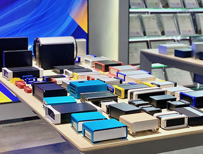
Here is the sizing bridge from NEC volume to a real aluminum box, using YONGU's standard junction box profiles (internal width is the PCB slot width published on each product page):
| Aluminum box (W × H × L, mm) | Internal width (mm) | Est. internal volume (in³) | Max 14 AWG (no device) |
| 64 × 25.5 × 80 | 60.6 | 5.7 | 2 |
| 88 × 38 × 100 | 84.2 | 16.0 | 8 |
| 106 × 54 × 150 | 100.0 | 43.2 | 21 |
| 120 × 75 × 40 | — | 17.6 | 8 |
| 150 × 115 × 50 | — | 44.4 | 22 |
| 200 × 150 × 70 | — | 113.0 | 56 |
Volumes are calculated from the external envelope minus a 1.7 mm wall on each face and 5 mm at each end, so they are conservative estimates — always confirm against the drawing or the volume marked on the box before a code inspection. Wall thickness and internal ribs vary by profile, and a gasketed lid reduces usable height further. The G05 aluminum junction box, the 64W25.5H box and the 106W54H case are typical of these profiles; the waterproof enclosure design guide covers gasket and gland layout.
Send your conductor count, device list and environment — we return a box with the NEC volume verified and the internal dimensions marked.
Samples 8–10 days · batch 15–30 days · US delivery 7–15 days · volume marked per NEC 314.16(A)(2) on request