English
 العربية
 Nederlands
 Français
 Deutsch
 Italiano
 日本語
日本語 한국어
한국어 Polski
 Português
 Русский
 Español




A UPS power bank is only as dependable as the box around it: the enclosure has to carry battery weight, vent heat, keep dust out, survive seismic anchoring, and give electricians clean access to AC, DC and comms circuits — all while passing the codes your inspector actually checks. This guide covers the five decisions that determine whether a custom UPS power bank case passes approval: mechanical layout, material and rating, thermal and fire containment, electrical access, and procurement details.

Mechanical Layout, Dimensions, and Mounting Options
Start with a dimensioned layout before any fabrication. Record the installed envelope (W×H×D), the internal cavity after panels, and service clearances — at least 100 mm behind the battery tray for cable bending and enough above the inverter for a service hand. Mark every cable entry (AC input, DC battery leads, comms, grounding lug) with its knockout or gland size and position. Deliverables matter more than renders: a dimensioned 2D drawing, STEP model, assembly view and hole-pattern template the installer can verify on site.
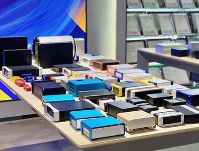
Mounting sets the load case. Rack-mount units bolt through front ears and rear supports; floor cabinets need a base frame anchored to the slab; wall units must clear the stud layout; outdoor pedestals carry wind and seismic loads. In U.S. installations, anchor design follows ASCE 7 and IBC provisions for nonstructural components — size the anchors for battery weight plus a lateral factor, never relying on sheet-metal walls to carry it. The instrument enclosure collection covers rack, desktop and panel styles, and the custom enclosure service delivers the CAD and hole-pattern files inspectors expect. For heavier packs, the industrial battery enclosure shows the reinforced base and tray layout a large bank needs.
Material Selection, Thickness, Environmental Ratings and Finish
Material follows the environment. Cold-rolled steel (1.0–2.0 mm) is the economical indoor choice — strong, weldable, powder-coated for protection; stainless 304/316 suits outdoor, coastal or washdown sites where coating damage means corrosion; aluminum gives a lighter, corrosion-friendly body with better heat transfer at higher sheet cost. Thickness is driven by load: battery shelves and base plates should run 1.5–2.0 mm (or use formed ribs) because pack weight concentrates there, while non-load side panels can drop to 1.0 mm.
Match the rating to the site: NEMA 1/2 (IP20/IP30) indoors, NEMA 3R for rain-sheltered outdoor, NEMA 4 (IP66) for direct exposure, NEMA 4X for coastal and chemical plants. Sealing decides whether the rating holds — gasketed doors with EPDM or silicone profiles, filtered vents or a pressure-equalizing breather, and gland-sealed entries. Specify the rating and the acceptance test (water spray, dust, salt fog) in the contract so inspection is not a dispute. For the steel-vs-aluminum question applied to battery boxes, see is the battery enclosure material a steel enclosure or an aluminum enclosure and what are the three types of lithium-ion battery enclosure.
Thermal Management, Ventilation and Fire/Thermal Containment
Size the cooling from the heat, not the fan. Estimate steady-state heat from inverter and charge losses, add the short-term peak, and convert to airflow with CFM ≈ watts ÷ (1.1 × ΔT °F). A 300 W load with a 15 °F ΔT needs roughly 18 CFM of real moved air after filter and duct losses; passive finned panels handle small loads, forced ventilation covers a few hundred watts, and hot outdoor sites may need an air conditioner with condensate handling.
| Thermal load step | Example value | Resulting spec |
| Inverter + charge losses | 300 W steady | Base thermal load |
| Fast-charge peak | +150 W short-term | Fan sizing at peak |
| ΔT budget | 15 °F internal rise | ≈ 18 CFM required |
| Derating | Filters + ducts ≈ 20% | Spec ≈ 22 CFM fan |
Battery thermal runaway is the failure mode that turns an enclosure into a fire source. Isolate the battery bay from the inverter with a thermal barrier, provide a vent path that exhausts hot gas outside the building (not into the rack), and place temperature, smoke and thermal-runaway detectors at the pack vent location. Active mitigation — heat-triggered fan shutdown, inerting or water-mist — follows the framework of NFPA 855 and UL 9540A, with NEC Article 706 requirements. The safety hazards in the storage process of lithium batteries article details the failure chain, and 220V portable UPS mobile energy storage power box features shows a working compartment layout.
Electrical Access, Cabling, Grounding, EMI/RFI and BMS Integration
Separate the circuits before routing. Allocate distinct zones for AC power, DC battery cabling and low-voltage control/comms, with physical separation or metal barriers so signal wiring is not coupled by power feeders. Provide glanded entries sized to the bundles, an internal busbar and breaker layout an electrician can trace without disassembly, and a dedicated grounding point. Per NEC Article 250, bond a single main ground lug or bus to the enclosure, rack and battery chassis, sized for fault current — never rely on paint-to-paint continuity. For EMI/RFI, add a filtered AC input panel, ground shielded comms cables at one end, and keep metal-to-metal door-to-frame contact (conductive gasket where needed).
BMS integration is what makes the box serviceable remotely. Reserve a DIN-rail or mounting area for the BMS module, route sensor wiring clear of power feeders, and terminate comms to labeled ports — Modbus RTU/TCP, CAN, SNMP or BACnet per facility standard. Deliver a standardized wiring diagram and signal pin table with the enclosure so field wiring is plug-and-play. The energy storage enclosure and UPS rackmount box show practical AC/DC compartment layouts.

Safety, Maintenance Access, Prototyping, Installation and Procurement
Design for the person servicing it in five years: front and rear doors or quick-release panels, drawer-style battery trays that slide out without full disassembly, visible breaker positions, and lockable isolation disconnects. Document the operating procedures — filter replacement intervals, battery inspection steps, safety labeling, PPE guidance — with the unit.
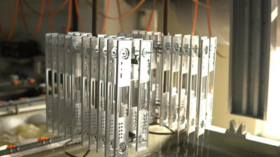
Compliance decides whether it deploys. For a UPS plus battery cabinet in the U.S., reference UL 1778 (UPS), UL 9540/9540A (ESS and thermal runaway), NFPA 70 (NEC Articles 706/710), NFPA 855, and IBC/ASCE 7 for seismic anchoring; specify certifications in the RFP and agree the third-party test plan before fabrication. Prototyping follows the sheet-metal path — laser cutting, bending, welding, powder coating — at 8–10 days for a sample and 15–30 days for batch; cost is driven by material grade, thickness and forming, certifications, special cutouts or coatings, and MOQ. See what factors need to be considered when customizing an instrument enclosure for the full decision list, and the enclosure design service covers the engineering review before tooling.
Need a Code-Ready UPS Enclosure? Get the Custom Engineering Package
Send your battery type and capacity, UPS rating, installation environment, target certifications and quantity — we'll deliver DWG/STEP drawings, assembly views, a thermal load calculation and wiring diagrams within 1 working day, plus a fixed quotation.
Samples 8–10 days · batch 15–30 days · US delivery via DHL/UPS/FedEx 7–15 days · certifications and test reports supplied with quotation
FAQs
How do I determine the correct enclosure dimensions and internal clearances for my UPS power bank system?
Stack the installed components — battery pack, inverter, BMS — then add 100 mm minimum rear clearance for cables, front service access, and 20–30 mm air gap around the battery module. Draw cable entries and busbar positions on a dimensioned layout, and confirm the envelope fits the rack U-height or floor footprint with the door fully open.
Which materials and thicknesses are recommended for indoor vs outdoor UPS enclosures in the U.S.?
Indoor: cold-rolled steel at 1.0–2.0 mm with powder coating is the economical default; aluminum is lighter with better heat transfer. Outdoor or coastal: stainless 304/316 or steel with a robust outdoor powder coat. Use 1.5–2.0 mm (or formed ribs) on battery shelves and base plates that carry the pack; 1.0 mm on non-load panels.
What thermal management strategies prevent battery thermal runaway in enclosed UPS installations?
Isolate the battery bay from the inverter with a thermal barrier, provide a vent path that exhausts hot gas outside the building, and place temperature, smoke and thermal-runaway detectors at the pack vent. Size forced airflow from the real heat load (CFM ≈ watts ÷ 1.1 ÷ ΔT °F), and design active mitigation — heat-triggered shutdown, inerting or water-mist — around NFPA 855 and UL 9540A.
What electrical access, connector layouts, and grounding practices ensure NEC and UL compliance?
Separate AC power, DC battery and low-voltage comms into distinct zones with metal barriers, use glanded entries sized to the bundles, and lay out busbars and breakers traceable without disassembly. Bond everything to one main lug or bus per NEC Article 250 (enclosure, rack, battery chassis), and use a filtered AC input plus shielded, single-end-grounded comms to control EMI.
Which certifications and standards should a custom battery enclosure meet for commercial deployment in the United States?
Plan for UL 1778 (UPS), UL 9540/9540A (ESS and thermal runaway), NEC Articles 706/710, NFPA 855 for ESS safety, and IBC/ASCE 7 for seismic anchoring. Specify certifications in the RFP, agree the third-party test plan before fabrication, and require test reports with the quotation.
How do I integrate BMS and monitoring systems (Modbus/CAN/SNMP) into the enclosure design for reliable telemetry?
Reserve a DIN-rail or mounting area for the BMS, route sensor and comms wiring clear of power feeders, and terminate to labeled ports (Modbus RTU/TCP, CAN, SNMP or BACnet). Deliver a standardized wiring diagram and signal pin table with the enclosure so integration is plug-and-play on site.
What are typical fabrication lead times and cost drivers for a custom UPS enclosure, and how can I speed up procurement?
Samples run 8–10 days and batch production 15–30 days from drawing approval. Cost is driven by material grade (stainless > aluminum > steel), thickness and forming, certifications and testing, special cutouts or coatings, and MOQ. Speed up by locking the BOM and test plan early, approving CAD in one pass, and ordering the standard finish before custom colors.