English
 العربية
 Nederlands
 Français
 Deutsch
 Italiano
 日本語
日本語 한국어
한국어 Polski
 Português
 Русский
 Español




Short answer: an aluminum junction box is the default choice for industrial sensor wiring because it combines IP65–IP68 sealing, inherent EMI shielding, corrosion resistance, and mechanical toughness in one housing — and it can be machined, gasketed, and terminated to your exact sensor layout. The right specification depends on four decisions: the environment (IP/NEMA rating and hazard classification), the cable entry scheme (M12/M8/RJ45 or cable glands), the number and type of sensors, and the grounding/EMC requirements. This guide walks through all five — compliance, materials, electrical integration, installation, and sensor-level design — with real products, quantitative tables, and a downloadable CAD path.

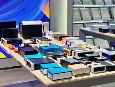
The reference product for this guide is the G05 aluminum junction box (75H body, wall/rack mountable, $29 list), part of the broader electronic enclosure and waterproof NEMA box collections. Where a higher IP rating or a smaller footprint is needed, the M-series and L-series boxes are cross-referenced.
Protection Ratings, Hazardous-Area Certification, and Compliance
Industrial sensor boxes live in two regulatory worlds at once: the IP system (IEC 60529) used globally and the NEMA 250 system used in the United States. They are not one-to-one equivalents — NEMA adds corrosion, ice, and oil-resistance tests that IP does not cover — but the mapping below is the working reference most US engineers use.
| IP Rating | What It Means | Closest NEMA | Typical Sensor Use |
| IP54 | Dust-protected, splash water | NEMA 12 / 13 | Indoor cabinet, light splashing |
| IP65 | Dust-tight, low-pressure water jets | NEMA 4 (approx.) | Wash-down areas, machine mounting |
| IP66 | Dust-tight, powerful water jets | NEMA 4 / 4X | Outdoor, hose-down, food & beverage |
| IP67 | Dust-tight, 1 m immersion 30 min | NEMA 6 | Flood-prone outdoor, ground-level |
| IP68 | Dust-tight, continuous immersion (mfr-specified) | NEMA 6P | Underwater, buried, marine |
Rule of thumb for US installations: specify NEMA 4X for any outdoor or wash-down sensor box — it adds corrosion resistance to the NEMA 4 water-ingress test — and use IP67/IP68 boxes only when submersion is a real risk. NEMA 4X is not automatically IP68; if you need both, ask for the IP test report. Our aluminum NEMA enclosure guide and the IP68 box explainer cover the test procedures in detail.
Hazardous-Area Certifications: Class/Division vs. Zone/ATEX/IECEx
If the sensor box goes near flammable gas, vapor, or dust, the enclosure itself must carry a hazardous-location rating. The US uses the NEC Class/Division system; the EU and most export markets use ATEX / IECEx Zone. They describe the same risk but with different boundaries — a Division 2 box is not automatically Zone 2, and vice versa.
| Risk Level | US (NEC) | EU / IECEx | Enclosure Protection Method |
| Hazard continuous / long periods | Class I, Div 1 | Zone 0 / Zone 20 | Flameproof Ex d, intrinsic safety Ex i |
| Hazard likely occasionally | Class I, Div 1 | Zone 1 / Zone 21 | Flameproof Ex d, increased safety Ex e |
| Hazard unlikely / short duration | Class I, Div 2 | Zone 2 / Zone 22 | Non-sparking Ex nA, restricted breathing |
Practical rule: for a standard aluminum junction box without an explosion-proof rating, the safe claim is Class I, Division 2 / Zone 2 when used with appropriately rated terminals and sealed cable entries. Division 1 / Zone 0–1 requires a certified flameproof (Ex d) enclosure — a different product class, not a standard junction box. Always confirm the certification body (UL, CSA, ETL, or other NRTL) and the exact rating on the product label, not just the marketing page.
Recommended Rating by Sensor Type and Mounting Location
| Sensor / Location | Min. IP | NEMA | Hazard Note |
| Indoor PLC cabinet sensor hub | IP54 | NEMA 12 | General purpose |
| Machine-mounted vibration / temp sensor | IP65 | NEMA 4 | Coolant/oil exposure |
| Outdoor weather station (temp, pressure, humidity) | IP66 | NEMA 4X | UV + corrosion |
| Food & beverage wash-down line | IP66/IP67 | NEMA 4X | Caustic cleaners |
| Underground / buried utility sensor | IP68 | NEMA 6P | Prolonged moisture |
| Refinery / chemical plant (gas area) | IP66 | NEMA 4X | Div 2 / Zone 2 minimum; verify rating |
Certificate Checklist for Your Purchase Spec
Before issuing a PO, require the supplier to provide:
• IP test report (IEC 60529) with test depth, duration, and pass/fail — not just a claimed rating
• NEMA 250 test report or UL 50 / UL 508A file number (for US installations)
• NRTL recognition (UL, CSA, ETL, TÜV) with the exact model covered
• RoHS and REACH declarations (REACH covers 233+ restricted substances for EU export)
• Material certificate (alloy and temper) and surface-treatment specification
• For hazardous areas: the ATEX/IECEx or UL Class/Div certificate with equipment group and temperature class
• Salt-spray test report (ASTM B117) for coastal or chemical-plant use
Material, Durability, Thermal and Corrosion Management
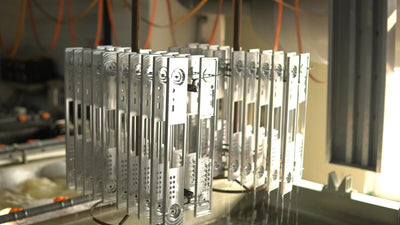
The alloy and finish determine how long the box survives in the field. For sensor junction boxes the choice is usually between 6061 (general purpose), 5052 (corrosion-prone environments), and 6063 (extruded profiles). The G05 and most YONGU junction boxes use 6061 or 6063 aluminum with anodized or powder-coated finishes.
| Alloy / Temper | Yield (MPa) | Thermal Cond. (W/m·K) | Corrosion | Best For |
| 6061-T6 | 276 | 167 | Good (anodized) | General industrial, machine build |
| 5052-H32 | 193 | 138 | Excellent (marine) | Coastal, salt air, chemical |
| 6063-T5 | 145 | 201 | Good (anodized) | Extruded profiles, heat spread |
| 316 Stainless | 205–690 | 16 | Superior | Extreme corrosion, pharma, marine |
Surface Treatment by Environment
| Finish | Thickness | Salt Spray (hrs) | Environment |
| Anodizing Type II | 5–25 μm | 500–1,000 | Indoor, mild outdoor |
| Hard anodize Type III | 25–100 μm | 1,000–3,000 | Wear, abrasion, heavy industrial |
| Powder coating (epoxy/polyester) | 50–100 μm | 1,000–2,000 | Outdoor, UV, color match |
| Alodine 1200S (chromate) | 0.5–3 μm | 200–500 | Conductive grounding, paint primer |
Environment-specific rules: for coastal or offshore use, specify 5052 aluminum with powder coating over anodize, or 316 stainless for the most aggressive salt spray. For chemical plants, use epoxy powder coat and verify compatibility with the specific reagents (acetone, chlorine, and strong acids attack even anodized aluminum). For high-temperature environments above 80°C, confirm the gasket rating (silicone to 200°C) and avoid standard powder coat above 120°C continuous. Our surface treatment service page lists the full anodizing and coating options.
Thermal Management: When the Box Is the Heatsink
Most sensor junction boxes contain only terminals and signal conditioners — low heat, no thermal problem. But when the box houses a power supply, a 4–20 mA loop converter, or an Ethernet switch, the aluminum housing becomes a passive heatsink. At ~167–201 W/m·K, aluminum spreads heat across the entire box surface far better than any plastic alternative. Design rules:
• Mount heat-generating components directly to the aluminum wall with a thermal pad (1–6 W/m·K) or thermal grease (3–10 W/m·K), not to a plastic internal bracket.
• Use standoffs or a metal mounting plate to transfer heat from the PCB to the enclosure wall.
• Do not add ventilation holes to an IP65+ box — they destroy the ingress rating. If you need airflow, switch to a vented NEMA 12 enclosure or add an external heatsink.
• For high-power components, specify a custom heat-sink panel machined into the lid or side.
• Calculate ΔT: a 10 W load on a 0.05 m² aluminum surface with natural convection rises roughly 15–25°C above ambient — verify with a thermal simulation or prototype measurement.
Vibration and Fatigue Acceptance Criteria
Sensor boxes on rotating machinery, pumps, or vehicles see continuous vibration. Acceptance testing follows IEC 60068-2-6 (sinusoidal, 5–500 Hz) or MIL-STD-810 Method 514 (random vibration). Typical industrial acceptance: 1–5g RMS over 10–500 Hz for 2 hours per axis, with no mechanical damage, no loosened fasteners, and continuous electrical continuity (<1Ω ground resistance throughout). For high-vibration mounts, add rubber isolators between the box and the mounting surface, and use thread-locking compound (e.g., Loctite 243) on all cover screws.
Electrical Integration, EMI/RFI Shielding, Grounding and Internal Termination
Terminal Block and Connector Selection
Inside the box, the standard is a DIN-rail-mounted terminal block (screw or spring-cage style) sized for the wire gauge. For sensor wiring, 16–24 AWG (0.5–1.5 mm²) is typical; power feeds may need 12–14 AWG. Spring-cage terminals (push-in) speed up field wiring and resist vibration better than screw terminals.
| Connector | Pin Counts | Typical Use | IP Rating (mated) |
| M8 | 3, 4, 6, 8 | Small sensors, proximity switches | IP65/IP67 |
| M12 A-coded | 4, 5, 8, 12 | DC sensors, actuators, general I/O | IP65/IP67/IP68 |
| M12 D-coded | 4 | Industrial Ethernet 100 Mbit | IP65/IP67 |
| M12 X-coded | 8 | Gigabit Ethernet, Profinet | IP65/IP67 |
| RJ45 (industrial) | 8P8C | Ethernet/IP, Modbus TCP | IP20 (IP67 with sealed jack) |
| Direct cable + gland | N/A | Multi-conductor, high current, custom | IP66–IP68 |
For a multi-sensor hub, a common layout is: M12 connectors on the lid or side for field sensors, a DIN-rail terminal strip inside for distribution, and a single M23 or direct multi-conductor cable for the trunk back to the PLC. Keep sensor signal wires (4–20 mA, thermocouple) separated from power leads by at least 50 mm inside the box, or route them through a divided internal cavity.
EMI/RFI Shielding: Aluminum's Natural Advantage
A bare aluminum enclosure provides 60–90 dB of shielding effectiveness across 30 MHz–1 GHz — enough for most industrial sensor applications. The catch: anodizing is electrically insulating, so a fully anodized box does not automatically make a good Faraday cage. To get the full shielding benefit:
• Mask the lid-to-body mating surfaces before anodizing, or apply Alodine (conductive chromate) to those surfaces.
• Use a conductive EMI gasket (knitted wire mesh, beryllium copper finger stock, or conductive foam) along the full perimeter of the lid seam.
• Bond every cable shield to the enclosure wall at the entry point (360° shield termination), not to a terminal block — a pigtail ground creates a high-impedance loop at RF.
• For plastic-lidded or hybrid boxes, add a conductive coating (copper/silver paint) or a bonded metal shield plate to the lid.
• Verify with a surface-resistance meter (target <0.1 Ω/sq on mating surfaces) and a shielding-effectiveness test per IEEE 299 or MIL-STD-285 if EMC margin is critical.
For a deeper walkthrough of shielding design, see our guide on how EMI-shielded enclosures work, and the EMI-shielding enclosure collection for pre-shielded options.
Grounding and Bonding per NEC / UL
US installations must follow NEC Article 250 (grounding) and UL 508A (industrial control panels). Key rules for a sensor junction box:
• The equipment grounding conductor (EGC) must be sized per NEC Table 250.122 — minimum #14 AWG (2.5 mm²) for 15 A circuits, #12 AWG (4 mm²) for 20 A.
• Use a dedicated ground bus bar inside the box, bonded to the enclosure with a star washer or a machined (non-anodized) contact point.
• Ground resistance between any accessible metal surface and the ground terminal must be <1Ω (UL 508A continuity test); for EMI-critical installs, target <0.1Ω.
• Do not rely on the hinge or mounting screws for grounding — use a separate bonding jumper.
• For shielded cables, terminate the shield at the enclosure wall (360°) and do not ground the shield at both ends unless the design specifically calls for it (ground loops).
Mounting, Cable Entry, Gaskets, Knockouts and Installation Best Practices
Cable Gland Sizing: Match Thread to Cable Diameter
The most common field failure is a cable gland that does not match the cable outer diameter — too loose and water gets in, too tight and the seal compresses unevenly. Use this pairing table:
| Gland Thread | Cable OD Range (mm) | Typical Wire | Torque (N·m) |
| M12 / PG7 | 3–6.5 | 2–4 core sensor cable | 0.8–1.5 |
| M16 / PG9 | 4–8 | 4–6 core, M12 trunk | 1.0–2.0 |
| M20 / PG13.5 | 6–12 | 6–12 core, multi-sensor trunk | 1.5–2.5 |
| M25 / PG16 | 9–16 | 12–18 core, power + signal | 2.0–3.5 |
| M32 / PG21 | 13–21 | Multi-conductor trunk, 20+ core | 3.0–5.0 |
Gasket Material Selection
| Material | Temp Range (°C) | UV / Outdoor | Oil / Fuel | Best Use |
| Silicone | -60 to +200 | Excellent | Poor | Outdoor, wide temp, food-grade |
| EPDM | -40 to +120 | Excellent | Poor | Outdoor, water, UV, steam |
| NBR (Nitrile) | -30 to +100 | Poor | Good | Machine tool, oil, hydraulic |
| FKM (Viton) | -20 to +200 | Good | Excellent | Chemical, high-temp, fuel |
| PU (Polyurethane) | -30 to +80 | Fair | Moderate | Abrasion, pneumatic, general |
Sealing sequence: (1) clean the gasket groove with isopropyl alcohol; (2) seat the gasket without stretching (stretching causes shrink-back and leaks); (3) tighten cover screws in a diagonal star pattern in 2–3 passes; (4) final torque per the table below. Replace gaskets every 2–3 years for outdoor IP67+ boxes, or immediately if they show cracking, compression set, or loss of elasticity.
Cover Screw Torque and Knockout Sizes
| Screw Size | Torque (N·m) | Notes |
| M3 (stainless) | 0.5–0.8 | Small lids, use thread locker |
| M4 | 1.0–1.5 | Most common cover screw |
| M5 | 2.0–3.0 | Large boxes, NEMA 4X |
| M6 | 3.0–5.0 | Heavy-duty, floor mount |
Standard knockout / conduit entry sizes for US installations: 1/2" NPT (≈21 mm hole), 3/4" NPT (≈27 mm), 1" NPT (≈34 mm). If you are machining custom holes, use a step drill or chassis punch — not a twist drill, which can walk and oval the hole, breaking the gland seal. Deburr every hole on both sides; a burr under a gland is a guaranteed leak path.
Field Installation Checklist
1. Verify box rating (IP/NEMA) matches the location spec before mounting.
2. Mount with stainless or zinc-plated hardware; use star washers at the enclosure bond point.
3. Drill / punch cable entries; deburr and clean.
4. Install cable glands with the correct thread sealant (PTFE tape or liquid sealant on NPT threads).
5. Pull cables; leave 150–200 mm service loop inside the box.
6. Terminate to DIN-rail blocks; route signal and power wires in separate zones.
7. Bond cable shields 360° at the gland; connect ground bus to EGC.
8. Seat gasket; tighten cover screws diagonally in 2–3 passes to specified torque.
9. Megger / continuity test: ground resistance <1Ω, insulation >100 MΩ.
10. Apply tamper seal / asset tag; record installation date and gasket batch for replacement tracking.
Sensor Integration Guides, Drawings, Supply Chain and Case Studies
Sensor Type Wiring Quick Reference
| Sensor Type | Signal | Connector | Box Note |
| Temperature (PT100 / thermocouple) | RTD / mV | M12 4-pin A-coded | Shielded pair, isolate from power |
| Vibration (IEPE / accelerometer) | 4–20 mA / IEPE | M12 4-pin | Coax or shielded, 360° bond |
| Pressure (gauge / absolute) | 4–20 mA / HART | M12 4-pin / direct | Intrinsic safety barrier if hazardous |
| Optical / photoelectric | NPN / PNP / IO-Link | M8 / M12 4-pin | Keep away from motor VFD cables |
| Ethernet / IO-Link master | 100 Mbit / GbE | M12 D/X-coded / RJ45 | Managed switch, shielded CAT6A |
Multi-Sensor Integration Example
A typical pump-monitoring skid uses one G05 junction box to aggregate: 2× vibration sensors (M12, IEPE), 1× PT100 temperature (M12, 4-wire), 1× pressure transmitter (4–20 mA, direct cable), and 1× Ethernet link back to the PLC (M12 D-coded). Inside, a 10-position DIN-rail terminal block distributes power and signals; all shields bond to the enclosure wall; the Ethernet cable runs in a separate corner of the box away from the 4–20 mA pairs. The box mounts on the pump skid with rubber isolators, cover screws torqued to 1.2 N·m (M4), silicone gasket, IP66 rated.
Troubleshooting quick path: if a sensor drops out, (1) check the M12 connection at the box — 70% of field faults are connector-related; (2) verify shield continuity with a multimeter from the sensor shell to the box ground (<1Ω); (3) inspect the gasket for compression set or debris; (4) check for water inside — if present, the gland seal or cover gasket has failed; (5) if the signal is noisy, verify signal/power separation and check for a VFD or motor cable routed within 50 mm of the sensor leads.

CAD Files, Custom Machining, and Ordering
Every YONGU junction box is available with a STEP / 3D model and 2D dimension drawing — request it with your inquiry and we send the files within 2 working days. Custom machining options include:
• M12/M8/RJ45 connector cutouts and threaded gland holes (any pattern)
• DIN-rail mounting bosses, internal PCB standoffs, and divider walls
• Hinged or screw-on lids, stainless hasps, tamper-evident seals
• Custom length / width / height via custom enclosure size
• Logo and labeling via silk-screen or laser engraving
• Conductive masking on mating surfaces for EMI grounding
Ordering fields to specify: model + size, alloy/finish, IP/NEMA rating required, hole pattern (attach drawing), connector types, gasket material, quantity, and destination (for certification and shipping). Lead times: samples with custom cutouts in 7–15 days; batch production in 15–30 days; EXW / FOB / DDP / DAP trade terms accepted; payment via T/T or PayPal (30% deposit, 70% before shipment).
Representative U.S. Application Examples
Example 1 — Midwest food & beverage plant, bottling line sensor hub. Problem: existing plastic junction boxes cracked after 18 months of daily caustic wash-down, causing sensor downtime. Solution: replaced with G05 aluminum boxes, powder-coated (food-safe polyester), IP66, silicone gaskets, M12 connectors, stainless hardware. Result: after 24 months in service, zero box failures, zero water ingress; wash-down cycle time unchanged. (Representative field scenario; actual results vary by installation.)
Example 2 — Gulf Coast oil & gas pump skid, outdoor vibration/temp monitoring. Problem: high temperature (45°C ambient), salt air, and Class I Div 2 area required a corrosion-resistant, EMI-shielded box with certified cable entries. Solution: 5052 aluminum box with hard anodize + powder coat, IP66, NBR gaskets, M20 cable glands, conductive-gasket lid, 360° shield bonding. Result: continuous operation through a Gulf summer with internal temp peaking at 62°C (well below the 85°C component rating), ground resistance measured at 0.08Ω. (Representative field scenario; actual results vary by installation.)
Need a sensor junction box specified to your exact application?
Send your sensor list, mounting location, IP/NEMA requirement, and target volume — or upload a CAD file. Our engineers respond within one working hour with a recommendation, a quote, and STEP/2D drawings. Samples ship in 7–15 days; certifications (RoHS, REACH, IP test report) included. EXW / FOB / DDP / DAP.
Request a Quote / Sample Box →
Email: export@yonggu-enclosure.com · Phone/WhatsApp: +86 17708670860
FAQs
Which NEMA and IP ratings are typically required for aluminum junction boxes used with industrial sensors in outdoor U.S. installations?
For most outdoor US sensor installations, specify NEMA 4X (corrosion-resistant version of NEMA 4), which maps approximately to IP66. For flood-prone or ground-level mounts, step up to IP67 (NEMA 6) or IP68 (NEMA 6P). Always require the actual IP test report — a NEMA 4X rating alone does not guarantee IP68.
How can I verify hazardous-area certifications for a junction box and determine whether I need Class/Division or Zone/ATEX compliance?
US installations follow NEC Class/Division; EU/export follows ATEX/IECEx Zone. Check the product label and certificate for the exact rating (e.g., Class I Div 2 Groups B/C/D, or ATEX II 3G Ex nA IIC T4). A standard aluminum junction box is typically suitable for Division 2 / Zone 2 with properly rated terminals and sealed entries. Division 1 / Zone 0–1 requires a certified flameproof (Ex d) enclosure — a different product. Require the UL/CSA/ETL certificate number and verify it in the NRTL database.
What cable gland sizes and M12/M8 connector options should I choose for common industrial sensors, and how do I size them to ensure proper sealing?
Most discrete sensors use M8 (3–4 pin) or M12 A-coded (4–5 pin); Ethernet uses M12 D-coded (100 Mbit) or X-coded (GbE). For direct cable entry, match the gland to the cable outer diameter — M12/PG7 for 3–6.5 mm, M20/PG13.5 for 6–12 mm, M25/PG16 for 9–16 mm. The cable must fall within the gland's stated range; if it is at the edge, go up one size. See the gland pairing table in Section 4 for full details.
What are the best practices for grounding and bonding aluminum junction boxes to minimize EMI/RFI and meet NEC and UL requirements?
Use a dedicated ground bus bar bonded to the enclosure at a machined (non-anodized) point with a star washer. Size the EGC per NEC Table 250.122 (minimum #14 AWG for 15 A). Keep ground resistance <1Ω (UL 508A) and <0.1Ω for EMI-critical installs. Terminate cable shields 360° at the cable gland — never via a pigtail. Do not rely on hinges or mounting screws for bonding; use a separate bonding jumper. See Section 3 for the full grounding procedure.
Which gasket materials and sealing procedures provide reliable long-term ingress protection, and what torque specs should installers use for cable glands?
Use silicone for outdoor/wide-temperature, EPDM for water/UV/steam, NBR for oil/machine-tool, and FKM (Viton) for chemical/high-temp. Clean the groove, seat without stretching, and tighten cover screws diagonally in 2–3 passes. M4 cover screws: 1.0–1.5 N·m; M20/PG13.5 glands: 1.5–2.5 N·m; M25/PG16: 2.0–3.5 N·m. Replace gaskets every 2–3 years outdoors or at any sign of cracking or compression set.
Where can I obtain CAD/STEP files, hole-pattern templates, and custom machining options for integrating specific sensors and brackets?
Request STEP/3D models and 2D dimension drawings with your inquiry — we send them within 2 working days. Custom machining includes M12/M8/RJ45 cutouts, gland holes, DIN-rail bosses, PCB standoffs, dividers, hinges, and custom sizes via our custom enclosure size service. Upload your drawing or hole list to request a quote.
How should I select surface finishes or coatings for aluminum boxes to prevent corrosion in coastal or chemical plant environments?
For coastal/salt-air: use 5052 aluminum with powder coating over anodize, or 316 stainless for the most aggressive sites. For chemical plants: use epoxy powder coat and verify compatibility with the specific reagents (chlorine, acids, and solvents attack bare and anodized aluminum). Require an ASTM B117 salt-spray report (target 1,000+ hours for coastal, 2,000+ for heavy industrial). See the finish table in Section 2 for full data.